Field Oriented Vector Control
AC Induction motors are relatively cheap and sturdy machines that are used in a wide variety of industrial applications; however, they require complex modern control techniques for dynamic operation. Traditionally, induction motors have been run at a single speed, which was determined by the frequency of the main voltage and number of poles in the motor.
Field Oriented Vector Control, developed in 1971 by Blashke, models the time varying control problem in the induction motor as a time-invariant DC motor equivalent control scenario. Through utilizing the Clarke and Park transformations and motor induction models, the stator current can broken into separate direct and quadrature components; where the torque and flux can be controlled separately.
Unlike scalar control, the stator frequency is not directly controlled. The transient response is very fast because the torque (controlled by the quadrature component of the stator) does not affect the flux.
The Benefits of Field Oriented Vector Control are listed below:
-Fast dynamic response to current transients/quick speed or torque changes
-Lower Energy Consumption (especially through SVPWM)
-Decoupled Control of Torque and Flux
-Wider range of control over all four speed quadrants
-Operation above base speed
-Can be operated without an analog rotor speed sensor
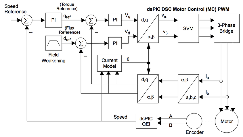
Steps for Indirect Vector Control (sample by sample)
1) The 3 phase stator currents are sensed and the rotor velocity is determined.
2) The 3 phase currents are converted into to a 2-axis alpha-beta coordinate system. These are the time varying direct and quadrature components.
3) The alpha-beta coordinates are rotated and aligned with the rotor flux angle using the rotor flux angle calculated from the previous sample.
4) Error signals are formed using from the torque and flux references and these signals are fed into separate PI controllers. The outputs of these controllers are the Vd and Vq.
5) A new rotor flux angle is calculated based on the motor speed, rotor electrical time constant, and the direct and quadrature current components
6) The Vd and Vq components calculated in step 4 are rotated back to the stationary reference frame using the new angle calculated in sample 5. This moves us back to alpha and beta voltage coordinates.
7) The Valpha and Vbeta are input into SVPWM and the duty cycles for inverter switching times are calculated.
8) The inverter outputs 3 phase currents to the motor.
Each of these blocks is explained in detail on the simulation page.
